RSS Feed

Reducing Valves

Reducing valves automatically reduce supply pressure to a preselected pressure as long as the supply pressure is at least as high as the selected pressure. The principal parts of the reducing valve are the main valve; an upward-seating valve that has a piston on top of its valve stem, an upward-seating auxiliary (or controlling) valve, a controlling diaphragm, and an adjusting spring and screw.

Reducing valve operation is controlled by high pressure at the valve inlet and the adjusting screw on top of the valve assembly. The pressure entering the main valve assists the main valve spring in keeping the reducing valve closed by pushing upward on the main valve disk. However, some of the high pressure is bled to an auxiliary valve on top of the main valve. The auxiliary valve controls the admission of high pressure to the piston on top of the main valve.
The piston has a larger surface area than the main valve disk, resulting in a net downward force to open the main valve. The auxiliary valve is controlled by a controlling diaphragm located directly over the auxiliary valve.

The controlling diaphragm transmits a downward force that tends to open the auxiliary valve. The downward force is exerted by the adjusting spring, which is controlled by the adjusting screw. Reduced pressure from the main valve outlet is bled back to a chamber beneath the diaphragm to counteract the downward force of the adjusting spring. The position of the auxiliary valve, and ultimately the position of the main valve, is determined by the position of the diaphragm. The position of the diaphragm is determined by the strength of the opposing forces of the downward force of the adjusting spring versus the upward force of the outlet reduced pressure. Other reducing valves work on the same basic principle, but may use gas, pneumatic, or hydraulic controls in place of the adjusting spring and screw.


Non-variable reducing valves, replace the adjusting spring and screw with a pre-pressurized dome over the diaphragm. The valve stem is connected either directly or indirectly to the diaphragm. The valve spring below the diaphragm keeps the valve closed. As in the variable valve, reduced pressure is bled through an orifice to beneath the diaphragm to open the valve. Valve position is determined by the strength of the opposing forces of the downward force of the pre-pressurized dome versus the upward force of the outlet-reduced pressure.

Non-variable reducing valves eliminate the need for the intermediate auxiliary valve found in variable reducing valves by having the opposing forces react directly on the diaphragm. Therefore, non-variable reducing valves are more responsive to large pressure variations and are less susceptible to failure than are variable reducing valves.

Valve Actuator

The actuator operates the stem and disk assembly. An actuator may be a manually operated handwheel, manual lever, motor operator, solenoid operator, pneumatic operator, or hydraulic ram. In some designs, the actuator is supported by the bonnet. In other designs, a yoke mounted to the bonnet supports the actuator.

Except for certain hydraulically controlled valves, actuators are outside of the pressure boundary. Yokes, when used, are always outside of the pressure boundary.

Valve Trim

The internal elements of a valve are collectively referred to as a valve's trim. The trim typically includes a disk, seat, stem, and sleeves needed to guide the stem. A valve's performance is determined by the disk and seat interface and the relation of the disk position to the seat. Because of the trim, basic motions and flow control are possible. In rotational motion trim designs, the disk slides closely past the seat to produce a change in flow opening. In linear motion trim designs, the disk lifts perpendicularly away from the seat so that an annular orifice appears.

Disk and Seat
For a valve having a bonnet, the disk is the third primary principal pressure boundary. The disk provides the capability for permitting and prohibiting fluid flow. With the disk closed, full system pressure is applied across the disk if the outlet side is depressurized. For this reason, the disk is a pressure-retaining part. Disks are typically forged and, in some designs, hard-surfaced to provide good wear characteristics. A fine surface finish of the seating area of a disk is necessary for good sealing when the valve is closed. Most valves are named, in part, according to the design of their disks. The seat or seal rings provide the seating surface for the disk. In some designs, the body is machined to serve as the seating surface and seal rings are not used. In other designs, forged seal rings are threaded or welded to the body to provide the seating surface. To improve the wear-resistance of the seal rings, the surface is often hard-faced by welding and then machining the contact surface of the seal ring. A fine surface finish of the seating area is necessary for good sealing when the valve is closed. Seal rings are not usually considered pressure boundary parts because the body has sufficient wall thickness to withstand design pressure without relying upon the thickness of the seal rings.

Stem
The stem, which connects the actuator and disk, is responsible for positioning the disk. Stems are typically forged nd connected to the disk by threaded or welded joints. For valve designs requiring stem packing or sealing to prevent leakage, a fine surface finish of the stem in the area of the seal is necessary. Typically, a stem is not considered a pressure boundary part. Connection of the disk to the stem can allow some rocking or rotation to ease the positioning of the disk on the seat. Alternately, the stem may be flexible enough to let the disk position itself against the seat. However, constant fluttering or rotation of a flexible or loosely connected disk can destroy the disk or its connection to the stem. Two types of valve stems are rising stems and nonrising stems, these two types of stems are easily distinguished by observation. For a rising stem valve, the stem will rise above the actuator as the valve is opened. This occurs because the stem is threaded and mated with the bushing threads of a yoke that is an integral part of, or is mounted to, the bonnet.

There is no upward stem movement from outside the valve for a nonrising stem design. For the nonrising stem design, the valve disk is threaded internally and mates with the stem threads.

Valve Bonnet

The cover for the opening in the valve body is the bonnet. In some designs, the body itself is split into two sections that bolt together. Like valve bodies, bonnets vary in design. Some bonnets function simply as valve covers, while others support valve internals and accessories such as the stem, disk, and actuator.

The bonnet is the second principal pressure boundary of a valve. It is cast or forged of the same material as the body and is connected to the body by a threaded, bolted, or welded joint. In all cases, the attachment of the bonnet to the body is considered a pressure boundary. This means that the weld joint or bolts that connect the bonnet to the body are pressure-retaining parts.


Valve bonnets, although a necessity for most valves, represent a cause for concern. Bonnets can complicate the manufacture of valves, increase valve size, represent a significant cost portion of valve cost, and are a source for potential leakage.

Ball Valves

A ball valve is a rotational motion valve that uses a ball-shaped disk to stop or start fluid flow. The ball, performs the same function as the disk in the globe valve. Whenthe valve handle is turned to open the valve, the ball rotates to a point where the hole through the ball is in line with the valve body inlet and outlet. When the valve is shut, the ball is rotated so that the hole is perpendicular to the flow openings of the valve body and the flow is stopped.

Most ball valve actuators are of the quick-acting type, which require a 90° turn of the valve handle to operate the valve. Other ball valve actuators are planetary gear-operated. This type of gearing allows the use of a relatively small handwheel and operating force to operate a fairly large valve.

Some ball valves have been developed with a spherical surface coated plug that is off to one side in the open position and rotates into the flow passage until it blocks the flowpath completely. Seating is accomplished by the eccentric movement of the plug. The valve requires no lubrication and can be used for throttling service.

Gate Valve

A gate valve is a linear motion valve used to start or stop fluid flow; however, it does not regulate or throttle flow. The name gate is derived from the appearance of the disk in the flow stream.

The disk of a gate valve is completely removed from the flow stream when the valve is fully open. This characteristic offers virtually no resistance to flow when the valve is open. Hence, there is little pressure drop across an open gate valve.

When the valve is fully closed, a disk-to-seal ring contact surface exists for 360°, and good sealing is provided. With the proper mating of a disk to the seal ring, very little or no leakage occurs across the disk when the gate valve is closed.

On opening the gate valve, the flow path is enlarged in a highly nonlinear manner with respect to percent of opening. This means that flow rate does not change evenly with stem travel. Also, a partially open gate disk tends to vibrate from the fluid flow. Most of the flow change occurs near shutoff with a relatively high fluid velocity causing disk and seat wear and eventual leakage if used to regulate flow. For these reasons, gate valves are not used to regulate or throttle flow.

A gate valve can be used for a wide variety of fluids and provides a tight seal when closed. The major disadvantages to the use of a gate valve are:
  • It is not suitable for throttling applications.
  • It is prone to vibration in the partially open state.
  • It is more subject to seat and disk wear than a globe valve.
  • Repairs, such as lapping and grinding, are generally more difficult to accomplish.

Globe Valves

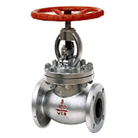
A globe valve is a linear motion valve used to stop, start, and regulate fluid flow. The globe valve disk can be totally removed from the flowpath or it can completely close the flowpath.

The essential principle of globe valve operation is the perpendicular movement of the disk away from the seat. This causes the annular space between the disk and seat ring to gradually close as the valve is closed. This characteristic gives the globe valve good throttling ability, which permits its use in regulating flow. Therefore, the globe valve may be used for both stopping and starting fluid flow and for regulating flow.

When compared to a gate valve, a globe valve generally yields much less seat leakage. This is because the disk-to-seat ring contact is more at right angles, which permits the force of closing to tightly seat the disk. Globe valves can be arranged so that the disk closes against or in the same direction of fluid flow. When the disk closes against the direction of flow, the kinetic energy of the fluid impedes closing but aids opening of the valve. When the disk closes in the same direction of flow, the kinetic energy of the fluid aids closing but impedes opening. This characteristic is preferable to other designs when quick-acting stop valves are necessary. Globe valves also have drawbacks.

The most evident shortcoming of the simple globe valve is the high head loss from two or more right angle turns of flowing fluid. Obstructions and discontinuities in the flowpath lead to head loss. In a large high pressure line, the fluid dynamic effects from pulsations, impacts, and pressure drops can damage trim, stem packing, and actuators. In addition, large valve sizes require considerable power to operate and are especially noisy in high pressure applications. Other drawbacks of globe valves are the large openings necessary for disk assembly, heavier weight than other valves of the same flow rating, and the cantilevered mounting of the disk to the stem.